RF Antennas 3D Engineering Hub
Size an antenna for any frequency and see its 3D radiation pattern: from 137 MHz weather satellites to 403 MHz radiosondes and microwave dishes.
- 8 tools
- 8 in 3D
- 8 with live charts
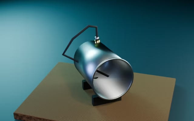
- CantennaSize a can waveguide antenna: cutoff frequencies, guide wavelength and probe position.Tool#cantenna#waveguide-antenna
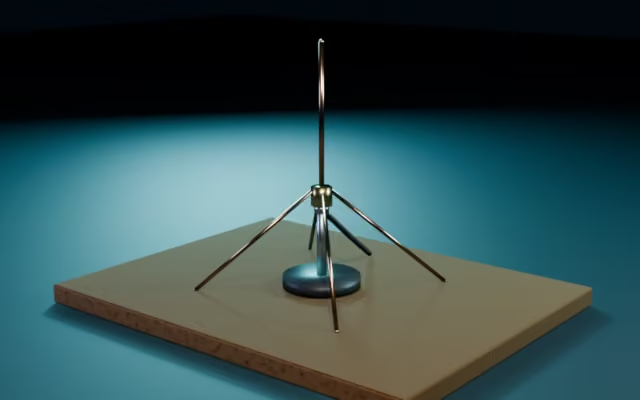
- Ground planeSize a quarter-wave ground-plane vertical with drooping radials and see the whip, hub, mast and doughnut lobe in 3D.Tool#ground-plane-antenna#quarter-wave-vertical
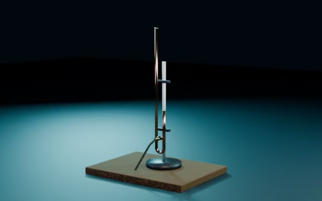
- J-poleSize a J-pole antenna and see its long radiator, matching stub, U bend and coax feed taps in 3D.Tool#j-pole-antenna#end-fed-dipole
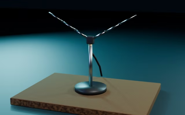
- V-dipoleCut the two legs of a V-dipole for 137 MHz weather satellites and see the bent legs, feed point and sky-facing lobe in 3D.Tool#v-dipole#weather-satellite-antenna
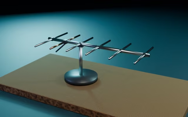
- YagiSize a DL6WU Yagi-Uda beam antenna and see its elements, boom, feed point and forward lobe in 3D.Tool#yagi-uda#directional-antenna
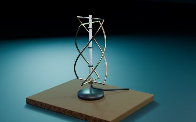
- Quadrifilar helix (QFH) antennaSize a quadrifilar helix antenna for satellite reception and see its two twisted loops in 3D.Tool#quadrifilar-helix#qfh-antenna
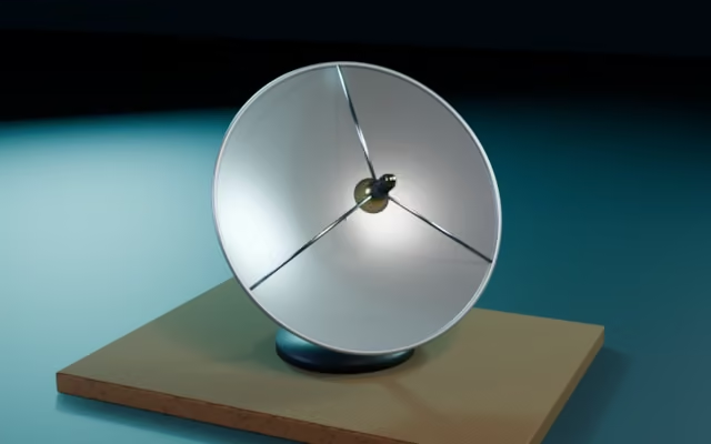
- Parabolic dishSize a prime-focus or offset satellite dish and see its focus, gain and beam in 3D.Tool#parabolic-reflector#focal-point
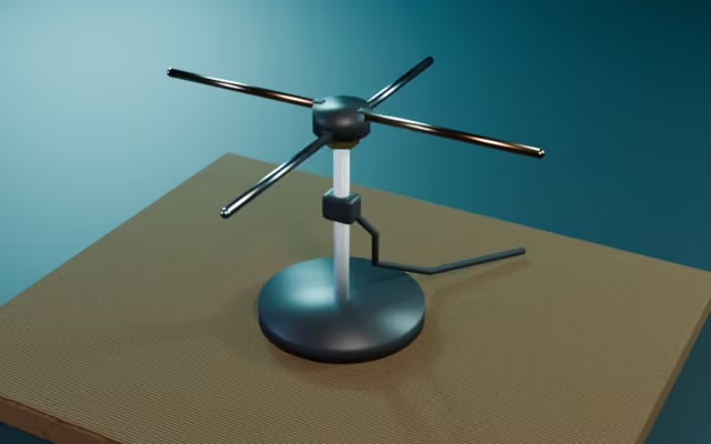
- Turnstile antennaDesign a crossed-dipole circularly polarised satellite antenna with a 90° phasing line.Tool#turnstile-antenna#crossed-dipoles
Core RF antenna engineering principles
- Free-space wavelength
λ = c / f ≈ 299.792 / f (MHz)Baseline for sizing half-wave and quarter-wave radiating elements. - Velocity factor
L = (c / f) × VF × 0.95Copper tubing is about 0.95, insulated wire about 0.90. - VSWR and return loss
VSWR = (1 + |Γ|) / (1 − |Γ|) ≤ 1.5Maximises power transfer into a 50 ohm SDR receiver. - Parabolic focus (f/D)
F = D² / (16 × d), f/D ≈ 0.35–0.45Optimal feed horn position for aperture illumination.
Related tools
3D RF Antenna Engineering Suite
8 wavelength-accurate NEC2 3D antenna models and radiation lobes for satellite, radiosonde, and amateur radio.
Key Astrometric & Technical Capabilities
- 8 NEC2 wavelength calculators (QFH, Yagi, Ground Plane, Turnstile, J-Pole, V-Dipole, Cantenna, Parabolic Dish)
- 3D far-field radiation lobes, half-power beamwidth, and coaxial impedance matching
- Optimized for 137.5 MHz weather satellites, 403 MHz radiosondes, and microwave feeds